
GEMINI
MEMORY LIGHTING CONTROL
OPERATOR'S HANDBOOK
EQUIPMENT
2.1 GENERAL
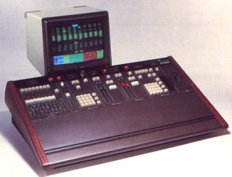
The basic Gemini system consists of two units: the Control Console and
a television monitor to act as the Video Mimic. Optional additional equipment
includes a stand, Multiplex Interface Units for connection to the dimmers,
a manual fader wing and a printer.
2.2 CONTROL CONSOLE
The Gemini control console is a self-contained unit which may be placed
on a desk, or mounted on a stand (available as an option). It requires
two mains inputs, one for the main control system and one for the memory
back-up unit; these supplies must be 220/240V or 110/120V A.C. single
phase (L. N. and E.). The mains inputs connect via I.E.C. 3-pin plugs
at the rear of the desk. Suitable mains cables are provided, but these
must be fitted with mains plugs by the user.
An illuminated power on/off switch is provided adjacent to the control
system mains input, and four switched mains outputs (via I.E.C. 3-pin
sockets) are provided for connection to peripheral equipment (Video Mimic,
etc.).
Other connections are as follows:
i) Data link to multiplexed dimmers or to Multiplex Interface units (whichever are provided). The cable should be two-core O.5mm2 with overall screen, fitted with 3-pin type XLR connectors wired as follows:
| Pin 1 | Screen | OV |
| Pin 2 | Red | Multiplexed Input (to desk) |
| Pin 3 | Blue | Multiplexed Output (from desk) |
The Control Desk is supplied with a suitable cable 5 metres in Length; longer (25 metre) cables are available if required.
ii) Output to Video Mimic.
Four 75 Ohm BNC output connectors are provided; three of these carry separate
R. G. B. signals for connection to the colour monitor supplied, while
the fourth carries a composite video output for use with a monochrome
monitor. A cable assembly for connection to the colour monitor is provided.
iii) Output to Printer. This is a standard RS232 signal and is connected via a 9-way D-type connector. A suitable cable is supplied with the printer, wired as follows:
| Pin 1 | Red | Signal GND |
| Pin 3 | Blue | TXD (to printer) |
| Pin 4 | Green | RXD (from printer) |
| Pin 9 | Yellow and screen | DTR |
iv) Audio Input to Effects Panel.
This connects via a 5-pin DIN socket, wired as follows:
| Pin 1 | Left-hand channel |
| Pin 2 | Audio OV |
| Pin 4 | Right-hand channel |
The Effects system is intended to be driven from the pre- amplifier stage
of a tape recorder, etc., and the input must not under any circumstances
exceed 5V peak-to-peak. If the source of the audio signal is mains powered,
use an isolating transformer to prevent earth loops.
In addition, there is a six-way Smiths Hypertac socket for connection
to a Rank Strand Rigger's/Designer's bus. See the appropriate User's Handbook
for details.
2.3 DIMMER INTERFACE
The Gemini dimmer control outputs are multiplexed and can drive any of
the dimmers in the Rank Strand range via a special interface which must
be fitted in each dimmer rack; this interface is supplied already fitted
to the Latest, multiplexed dimmers.
Alternatively, the system may be used with the Tempus M24 Multiplex Interface
unit. This produces the dimmer control signals for 24 Lighting channels
and will also accept inputs from another Lighting control system, e.g.
an AMC desk; if the second system is connected in this way, its contribution
combines with the output of Gemini on a 'Highest-takes-precedence' basis
and may be recorded in the Gemini memories.
2.3.1 Multiplex Interface Unit
Two types of Multiplex Interface Unit are available: one intended for
use with Tempus dimmer packs and control desks, and the other for use
with other types of equipment (e.g. Permus dimmers and ACT control desks).
Each unit provides control outputs for 24 dimmers, the units linking together,
so that only a single connection is necessary from the Control Console.
2.3.1.1 Connections
Each Multiplex Interface unit requires a mains input of 220/240V or 110/120V a.c. single phase (L. N. and E.), which connects via an I.E.C. 3-pin plug. A suitable mains lead is provided, but this must be fitted with a mains plug by the user. An adjacent 'Power On' indicator illuminates when the supply is connected.
The data link from the Control Console connects to a three-pin XLR plug (see Fig. 2.3.1), wired as described in section 2.2(i). If more than one Interface unit is used, they should be linked together by connecting the Multiplex Output (EXTENSION O/P) socket on one unit to the MULTIPLEX IN plug on the next as shown in the diagram. A cable for this purpose, 0.5 metres long, is provided with each Multiplex Interface unit. With the system operating correctly, the 'Communication' indicator (MUX OK) illuminates.
The units for use with Tempus dimmers and control desks are fitted with four control cables, one for each group of six channels (i.e. 1-6, 7-12, etc.). Each cable is fitted with the necessary 8- pin plug, wired as shown in Fig. 2.3.2, for connection to a Tempus dimmer pack. The control cable for the corresponding channels on the Tempus desk plugs into an 8-pin socket above and to the left of each cable outlet.
The other type of unit has two 2S-way D-type connectors labelled OUTPUT 1-24 and INPUT 1-24 for connection to the dimmers and the manual desk respectively. Suitable connectors and prewired cables are available from Rank Strand; wiring details are given in Table 2.3.3.
Table 2.3.3
| Dimmer | Pin | Colour |
|---|---|---|
| 1 | 1 | Red |
| 2 | 2 | Blue |
| 3 | 3 | Green |
| 4 | 4 | Yellow |
| 5 | 5 | White |
| 6 | 6 | Black |
| 7 | 7 | Brown |
| 8 | 8 | Violet |
| 9 | 9 | Orange |
| 10 | 10 | Pink |
| 11 | 11 | Turquoise |
| 12 | 12 | Grey |
| 13 | 13 | Red/Blue |
| 14 | 14 | Green/Red |
| 15 | 15 | Yellow/Red |
| 16 | 16 | White/Red |
| 17 | 17 | Red/Black |
| 18 | 18 | Red/Brown |
| 19 | 19 | Yellow/Blue |
| 20 | 20 | White/Blue |
| 21 | 21 | Blue/Black |
| 22 | 22 | Orange/Blue |
| 23 | 23 | Yellow/Green |
| 24 | 24 | White/Green |
| Common | 25 | Orange/Green |
Other combinations of equipment are possible, but may necessitate the
construction of special cables and/or distribution boxes. Connectors of
various types are available for this purpose.
Note: The dimmers from the current Rank Strand range require a control
voltage of -10V (full) to OV (zero). For systems using other types of
dimmers, Multiplex Interface units giving different control voltage outputs,
positive or negative, are available.
2.3.1.2 Setting-up
Before the Multiplex Interface Units may be used the Channel Group Selector
on each must be set to the required group of 24 dimmer numbers. The selector
is normally set before despatch, but may easily be adjusted by the user
if necessary.
Access to the selector switch requires the use of a small electrical screwdriver and is via a hole (labelled UNIT NO. - see Fig. 2.3.1) in the connector panel. The switch starts at 0 for channels 1-24 and should be turned clockwise one position for each additional 24 channels (see Fig. 2.3.4). As a reminder, the switch setting may be noted on the adjacent panel using a 'Chinagraph' pencil or an adhesive label.
2.4 ENVIRONMENT
The Gemini system will operate in ambient temperatures within the range
0ºC to 35ºC. All electronic components gradually suffer an ageing
process which is accelerated as the temperature rises, i.e. the higher
the ambient temperature, the more likely faults become. Similarly, wide
fluctuations in temperature will adversely affect the reliability of the
system. To maximise system reliability and minimise operator fatigue and
discomfort, an operating temperature between 18ºC and 25ºC is
recommended. Relative humidity should be between 10% and 90% (non-condensing).
The cleanliness of the surroundings has a direct effect on the life expectancy
of the system. Excessive dust and fluff obstruct ventilation and accumulation
of cigarette ash can cause partial short circuits.
Both the control panel buttons and the slider faders may be damaged by
an accumulation of grime, smoke or other contaminants. In particular,
liquids must not be spilt on the equipment, as the effect on the electronics
immediately below could be destructive. In the event of any liquids being
spilt onto the electronics, power must be turned off immediately; then
notify the Rank Strand service department.
The paint finish of the equipment will be damaged by direct heat such
as cigarettes or soldering irons. To clean, a judicious application of
anti-static aerosol cleaner is suitable. Under no circumstances should
spray polishes be used near the panels as they may destroy the slider
faders.
If a carpet is fitted in the control room, suitable precautions should
be taken to ensure that this does not lead to a build-up of Static Electricity.
ALL wool carpets or synthetic carpets with woven-in conductive threads
overcome this problem. Alternatively, anti-static treatments for nylon
or polyester carpets are available.
2.5 INSTALLATION
WARNING: Rank Strand Gemini Lighting control equipment must be
properly earthed if it is to function correctly. IT IS ESSENTIAL THAT
EARTH BE AT THE SAME POTENTIAL AT ALL POINTS IN THE SYSTEM. If this is
not the case, circulating currents may be generated in the signal earth
connections, leading to fluctuating Light Levels and, in extreme cases,
severe damage to the equipment.
In cases where the earth is provided via the supply neutral, all units
(i.e. Console, Manual Fader Wing, Multiplex Interface units, Effects unit
and dimmers) should ideally be powered from the same source via adequately
rated three core (L. N. E.) cable. If this is not possible, a single earth
point must be chosen and all the units earthed ONLY AT THIS POINT (see
Fig. 2.5.1). The conductors used must be able to carry any potential fault
current.
If damage is caused as a result of failure to observe the above recommendations,
any warranty will be invalidated. If in doubt, your Local Rank Strand
agent will be pleased to advise.
i) Assemble the stand (if provided), as described in section 2.4.
ii) Install the dimmers and connect the dimmer loads in accordance with the instructions supplied with the racks.
iii) If Multiplex Interface units are provided, connect the outputs of these to the appropriate dimmer control inputs. On installations using Tempus dimmers the output cables simply plug into the dimmer packs (extension cables are available for use where the dimmers are further than 2 metres away from the desk). Where other types of dimmer are used, the racks must be 'hard-wired'; the colour codes used in the cable supplied for the purpose by Rank Strand are given in Table 2.3.3.
iv) Decide which dimmer rack or Multiplex Interface unit will serve which group of channels and set the Channel Group Selector on each accordingly.
v) If Multiplex Interface units are to be used for connection of a Manual Fader Wing, connect the appropriate outputs of the Latter to the Multiplex Interface units. As in the case of the dimmers, the output cables from Tempus desks simply plug into the appropriate sockets on the Multiplex Interface units, while other types of desk must be hard-wired; refer to Table 2.3.3 for wiring details.
vi) Connect the data Link from the Control Console to one of the dimmer racks or Multiplex Interface units (as appropriate); choose whichever unit is the most convenient. Link all the units together as shown in Fig. 2.5.2.
vii) Connect the video mimic to the Control Console.
viii) Connect a mains supply to each part of the system and switch on (ideally, this should be controlled from a central on/off switch). Adjust the brightness and contrast of the video monitor to obtain a clear display.
2.6 ASSEMBLING THE STAND
1) Remove the screws from the ends of the 'ladder' section. Fix the legs
to the ladder section using these screws (see Fig. 2.6.1).
2) Lower the Gemini control console onto the stand; the wooden end panels
rest on the top of the legs. Fix the console in place using the screws
supplied.
3) Adjust the four feet to prevent the assembly wobbling.
4) Dismantle the two clamps supplied and use them to fix the monitor support
to the ladder section as shown in the diagram. position the monitor support
as required.
5) Fit the monitor tray to the top of the monitor support; tighten the
locking bolt to secure. Place the monitor on the tray, locating the feet
in the holes in the tray; connect the monitor to the console.
2.7 SPECIFICATION
2.7.1 Control Console
| Power input | 220V-240V or 110V-120V, 47-63Hz. |
| Desk output - Multiplexed analogue link via
2-core screened cable. |
|
| Control Channels | 50, 80, 96, 100, 120, 140, 144, 160 or 180 channels. Switch selectable. |
| Operating Environment | Temperature, OºC to 35ºC. Maximum relative humidity, 10% to 90% (non-condensing). 'Office' level cleanliness. |
| Processors | M68BO9: 3-bit data, 16-bit address. TMS320: 16-bit data, 12-bit address. |
| Cycle Time | Executive: typically 48ms. Contact scan: typically 12ms. |
| Fade Processing Accuracy | 16-bit. |
| Recording Accuracy | 8-bit (256 step). |
| Output Accuracy | 8-bit (256 step). |
| Fast Access Memory. |
Low-power semiconductor, battery-maintained for a minimum of one
month. Number of memories available depends on number of channels in use in each memory. A constantly updated display of memory used is shown on the Video Mimic. |
| Video Mimic Output. | Separate Red, Green and Blue, 1V positive composite video, 625/525
Line, 50/60Hz field; sync on Green. A separate monochrome output of
1V composite video is also provided. Connection is via 75 ohm BNC
sockets. |
| Floppy Disc (optional) | Uses Shugart SA300 3.5" Single Sided, Single Density soft-sectored Diskette. |
| Dimensions | Width : 970mm Depth : 560mm Height : 250mm Height when mounted on stand: 850mm Height including monitor on stand: 1190mm Clearance required at rear - for connectors : 100mm for monitor : 440mm Cut-out for desk-top mounting: 910mm Maximum thickness of desk-top: 25mm |
2.7.2 Video Monitor
| Dimensions | Width: 380mm Depth: 420mm Height: 330mm |
2.7.3 Multiplex Interface Unit
Power input - 220V-240V or 110V-120V, 47-63Hz.
Control input - Multiplexed analogue Link via 2-core screened
cable. Dimmer drive outputs
- OV (Off) to -10V (Full) via 10k ohm and silicon
diode.
- Optionally OV (Off) to +10V (Full) via 1k ohm and
silicon diode.
- Other control voltages are possible, within the Limits +/-15V.
Connection is via 4 x 2m Long control cables, each terminated in an 8-pin
'BLeecon' plug to mate with Tempus dimmer packs, or via a 25-way 'D' type
connector.
Input from Manual Fader Desk or Wing.
- As for dimmer drive outputs. Control Channels.
- One Multiplex Interface unit is required for each 24 channels.
Dimensions - Width : 280mm Depth : 75mm
Height : 200mm
Clearance required at front: 110mm