
GEMINI
MEMORY LIGHTING CONTROL
OPERATOR'S HANDBOOK
CHAPTER 5
MEMORY BACK-UP SYSTEM
5.1 INTRODUCTION
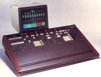
The Gemini Memory Back-up system is designed to provide simple control
facilities which permit continued operation in the unlikely event of failure
of the main console. It operates in a similar way to the pin matrix hitherto
provided as a back-up to larger memory systems, but features ten 'presets',
each consisting of eight electronic on/off memories (R - z). Eight 'Patch'
master faders are provided, one for each of the eight memories in the
selected Preset.
The system can control up to 384 dimmers and these are assigned to the
faders as required, using a keypad and an on/off button; alternatively,
the current lighting state may be 'copied' onto the selected fader, dimmers
above 10% intensity being set On and the remainder Off. The memories will
retain their contents for at least a week if the equipment is not used.
WARNING: When the Back-up system is in use, the Gemini Channel-to- dimmer
patch is NOT taken into account. For this reason, lighting channels are
refered to as 'Dimmers' throughout this chapter.
5.2 OPERATION
5.2.1 Switching the System On
The Back-up system does not have an On/Off switch and comes into operation
as soon as power is applied; it will not however be able to control lighting
unless the latching BACK-UP button is illuminated. When the Back-up system
is selected it has complete control of the lighting, the multiplexed output
from Gemini being disconnected.
On power-up, the keypad will be cleared and the Preset which was selected
on power-down will be automatically re-selected, together with Patch Master
R. Otherwise the initial state will depend on the settings of the controls.
The message 'POWER-UP OK' will pass across the DIMMER display window to
show that the equipment is functioning correctly; this message may be
cleared by pressing any key on the keypad, with the exception of '0/1',
' >' and '+'. Error messages are also possible - see section 5.3.
5.2.2 Preset Selection
The required Preset is selected by means of the PRESET button to the right
of the DIMr'ER display. The first operation of this button displays the
number of the currently selected Preset; the number of the Preset required
(1-10) may then be entered and the selection changed by pressing PRESET
a second time. If PRESET is pressed a second time without entering a new
number, the Preset selection will remain unchanged.
If the Back-up system is actually controlling dimmers when the second
operation of the PRESET button takes place, the dimmer levels will normally
change immediately to those in the newly selected preset, taking into
account the settings of the Patch Master faders. If continuity of lighting
is required, the lighting assigned to one or more Patch masters may be
retained by holding the corresponding SELECT buttons down while the PRESET
button is operated the second time. This is best illustrated by a practical
example:
The current lighting is under the control of Patch masters Y and Z, master
R to X being set to zero. The next scene is to be lit by masters Rand
S, using the lighting stored in Preset 4, and a slow fade to the new lighting
is required. First the PRESET button is operated and Preset 4 is selected;
then the SELECT buttons above masters Y and Z are pressed and, without
releasing them, PRESET is operated a second time. Masters R to X have
now been loaded with the corresponding lighting from Preset 4, but Y and
Z are unchanged. Y and Z may now be faded down and Rand S up to perform
the slow fade. When the change is complete, pressing PRESET twice will
reload all the Patch masters, including Y and Z, but as R to X have already
been loaded and Y and Z are now at zero, there will be no visible change.
5.2.3 Patch Masters
Each master fader has overall proportional control of a patch memory in
which dimmers may be set either On at full or Off.
Dimmers may be assigned to the master faders by means of the keypad to
the right of the faders. The requi red master mlJst fi rst be selected
by pressing the corresponding SELECT button in the row at the top of the
panel; the associated indicator lights to show the current selection.
Only one can be selected at a time.
Dimmer numbers are called-up using the numeric keys on the keypad in the
same way as on a calculator and the digits entered appear in the DIMMER
display window above the keypad. It is not possible to enter numbers greater
than 180, all but the last digit being ignored if this occurs. The dimmer
selection may be cleared by pressing the 'CL' key.
Once a dimmer has been selected, it may be set On or Off in the selected
patch memory by operating the '0/1' key; the indicator (ON) beside the
DIMMER window Lights if the dimmer is On. The '0/1' key has an alternate,
'toggle' action, each operation setting the selected dimmer On if it is
currently Off, or Off if it is On.
Dimmers may also be seLecterl by pressing the '+1' and NEXT ON keys. The
'+1' key selects the next dimmer in numeric sequence; note that if the
DIMMER window is blank this will be dimmer 1. The NEXT ON key finds the
next dimmer which is assigned to the selected master; this is most useful
for checking which dimmers are assigned to each master.
5.2.4 Selection of Groups of Dimmers
Several dimmers may be selected at once by using the '+' (Plus) and '>'
(Thru) keys. For example, to assign dimmers 5 and 17 to fader T, first
press SELECT button T and then enter 5, '+', 17 on the keypad, followed
by '0/1'. Similarly, 9, '+', 21, '+', 45 will allow dimmers 9, 21 and
45 to be set On or Off in the selected patch memory. Note that the ON
indicator shows the current state, in the selected memory, of the last
dimmer entered. When the '0/1' key is operated, all of the selected dimmers,
whatever their previous state, will be set to the same state, i.e. the
new state of the dimmer whose number is shown in the DIMMER window.
A range of dimmers may also be selected. For example, to select dimmers
20 to 30 inclusive, enter 20, '>' (Thru), 30.
5.2.5 Load Output
Dimmers may also be assigned to the selected fader by using the LOAD button
beside the DIMMER display window. When this button is operated, the Gemini
system output, including the contribution of a Manual Fader Wing if this
is provided, (i.e. the state shown on the 'OUTPUT' display on the Gemini
Video Mimic), is 'copied' onto the selected fader, with dimmers above
10% Level being set On and the remainder Off. The dimmers already assigned
to the selected fader will be over-written.
Note that because the dimmers allocated to a Patch Master may only be
On at full or Off, a Lighting scene copied to the Back-up System using
LOAD will not normally be identical to the corresponding scene on Gemini.
However, a compromise can usually be produced by allocating the various
dimmers to different Patch Masters and setting these to appropriate levels.
5.2.5.1 Blind Record
The LOAD button can also be used while the Back-up system is in use, for
recording 'blind', into a Preset which is not currently selected. Press
the PRESET button once, select the required Preset and then operate LOAD;
the On/Off states of the dimmers contributing to the current lighting
scene will be copied into the currently selected Patch memory in this
Preset, without disturbing the current Lighting. To return to normal control
press the CL button on the keypad and then operate the PRESET button a
second time.
5.3 ERROR MESSAGES
Two error messages are possible on power-up, replacing the 'POWER- UP
OK' message which normally appears in the DIMMER display window. These
messages are as follows:
DATA FAIL - An error has been found in the memory. This will normally
occur if the equipment has not been used for over a week; the memories
may be corrupted, but the system is otherwise fully functional. If, however,
this message appears when the system is in regular use, notify your Local
Rank Strand service agent.
The message may be cleared by pressing any key on the keypad, with the
exception of '0/1', ,>, and '+'; it will, however, reappear when the
system is next used unless the memory has changed.
PROM FAIL - An error has been found in the microprocessor program; notify
your Local Rank Strand service agent.